
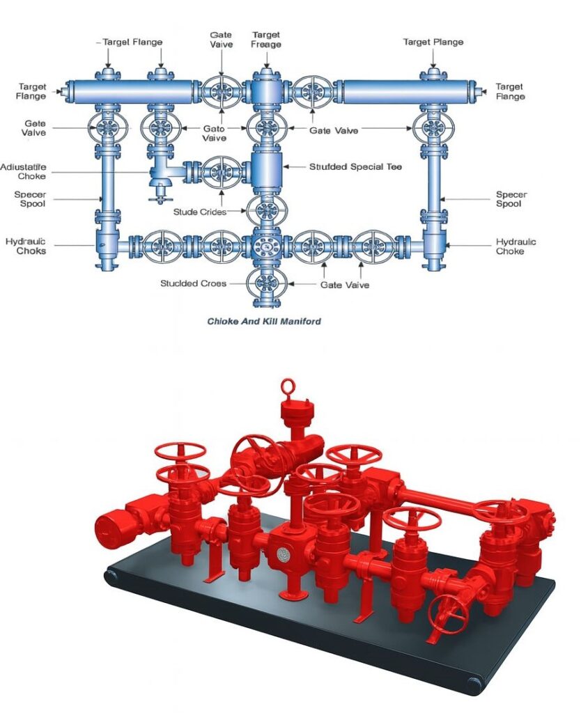
The Choke and Kill Manifold is a vital part of the well control system, designed to manage pressure during drilling operations—especially during kicks or wellbore influx situations.
Choke – The Basic Principle
A choke introduces a variable restriction in the wellbore fluid path to maintain backpressure on the formation. Adjusting the choke helps control flow rate and bottom-hole pressure, enabling safe kick circulation and avoiding blowouts.
Think of it like controlling a water hose with your thumb to regulate pressure and direction.
Key Components & Their Functions
- Target Flange
Function: Connects the manifold to external lines like choke and kill lines.
Example: Enables safe fluid transfer during a kill operation through the kill line.
- Gate Valve
Function: Isolates individual flow paths or components within the manifold.
Example: Shut off upstream/downstream flow to replace a choke without disturbing well pressure.
- Adjustable Choke
Function: Manually controlled choke to vary flow resistance and maintain pressure.
Example: Used to gradually circulate formation influx at controlled backpressure during a well control event.
- Hydraulic Choke
Function: Remotely operated adjustable choke—safer for HPHT wells.
Example: Enables choke adjustments from the driller’s console during kicks, minimizing manual risk.
- Studded Cross / Tee / Special Tee
Function: Forms flow junctions and structural layout for manifold routing.
Example: Allows parallel routing to flare line and separator during multipath circulation.
- Spacer Spool
Function: Provides vertical or horizontal spacing and alignment between manifold components.
Example: Aligns components like a choke and valve that differ in elevation or thread pattern.
Why the Choke Manifold Matters
Controls kick pressures
Routes flow to flare or separator
Enables soft shut-in
Provides dual flow paths (redundancy)
Safely bleeds off excess pressure
IWCF Quick Insights:
Why 2 chokes?
Backup choke ensures redundancy if one fails.
Choke in BOP system?
To maintain backpressure and circulate out kicks safely.
API 53 Spec – Bleed Line?
Diameter must be at least equal to the choke line for safe bypass.
Best Practices Onsite:
Daily valve checks
Grease moving parts regularly
Fully operate valves to detect sticking
Keep choke/kill lines clean to prevent plugging
Explore schematic and field setup for better clarity.
Your Turn
Manual or hydraulic choke—what’s your go-to in the field?
How do you test your choke manifold under API 53 compliance?